

1. Body

Attained by hot stamping or turned from solid bar, the body of the valve constitutes the external casing of the safety device.
Bodies are available in different sizes and surface finishes, supplied with the “Made in Italy” mark, a symbol of the highest quality
standards, reliability and Italian excellence. Ritmonio guarantees utmost quality of raw materials used and full observance of applicable
standards.
2. FLOW CONTROL DEVICES
The flow control device allows the water to flow from the feeding conduits into the water heater while limiting or preventing the backflow. Starting from the selection of materials, flow control devices can be customised according to customers’ needs.

Stand-by position
Flow control device in stand-by position.

Water heating supply position
It allows water to flow from the network to the water heater whenever there is a drop in pressure therein of 0.1 bar (0.01 Mpa).

Back flow position towards the network
It allows hot water to flow back into the feeding pipes whenever the differential pressure between the inside of the water heater and the network exceeds 1 bar (0.1 Mpa).
In any case, the water is guaranteed to flow back into the feeding pipes due to differential pressure exceeding 2 bar (0.2 Mpa).
Available versions
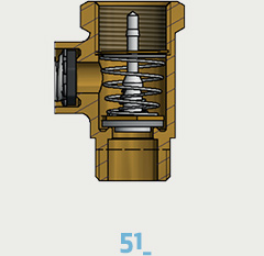
Flow control device for valve
G 3/8”
Available version:
51 = Flow control device, allows water to flow from the network to the water heater when there is a pressure drop therein of 0.1 bar (0.01 MPa).
It prevents the water from backflowing into the feeding pipes whenever the differential pressure between the inside of the water heater and the network is less than 1 bar (0.1 MPa).

Flow control device for valve
G 1/2” and valve G 3/4”
Available version:
54 = Flow control device, allows water to flow from the network to the water heater when there is a pressure drop therein of 0.05 bar (0.005 MPa). It prevents water from backflowing into the feeding pipes whenever the differential pressure between the inside of the water heater and the network is less than 1 bar (0.1 MPa).
89 = Flow control device, allows water to flow from the network into the water heater when there is a pressure drop therein of 0.1 bar (0.01 MPa). It prevents water from backflowing into the feeding pipes whenever the differential pressure between the inside of the water heater and the network is less than 1 bar (0.1 MPa).
99 = Flow control device with brass needle, allows water to flow from the network into the water heater when there is a pressure drop therein of 0.1 bar (0.01 MPa). It prevents water from backflowing into the feeding pipes whenever the differential pressure between the inside of the water heater and the network is less than 3 bar (0.3 MPa).

Non-return device for valve
G 1/2” and valve G 3/4”
Available version:
66 = Non-return device with brass needle, allows water to flow from the network into the water heater when there is a pressure drop therein of 0.1 bar (0.01 MPa). Prevents backflow.
67= Non-return device with plastic needle, allows water to flow from the network into the water heater when there is a pressure drop therein of 0.1 bar (0.01 MPa). Prevents backflow.

Ball non-return device
Available version:
77 = Ball non-return device, allows water to flow from the network into the water heater. Prevents backflow.

Flow control device for valve
Available version:
70 = Standard flow control device, allows water to flow from the network into the water heater when there is a pressure drop therein of 0.1 bar (0.01 MPa). It prevents water from backflowing into the feeding pipes whenever the differential pressure between the inside of the water heater and the network is less than 1 bar (0.1 MPa).
3. PRESSURE SAFETY DEVICES
Constant research and innovation allows Ritmonio to offer high performing products. Our safety devices limit the increase in pressure inside the water heater when reaching the predefined calibration value in the safest and most efficient manner possible. During the assembly phase, the values are calibrated and checked using an automated system before the packaging phase. In this manner, high quality standards can be met which have always distinguished Ritmonio’s products worldwide.

Safety device for Bottom valves
Available version:
11= Standard
22= Oversized

Safety device for Top valves
Disponibile nella versione:
S1= Standard
S2= Maggiorato

Safety device with lever
Available version:
33= Standard
44= Oversized

Safety device with lever and anti-drop system *
Available version:
3S= Standard
4S= Oversized
* ![]() RITMONIO PATENT
RITMONIO PATENT
4. COMPONENTS AND VARIANTS
In addition to technical customisations, Ritmonio offers its customers a vast range of components with different options to customise the products. The various colours of the sealing disks and drain levers give an original design in addition to distinguishing the Ritmonio valves with various features to make them immediately recognisable.

Sealing disk
Ensures anti-tampering of the safety device.
Available version:
– Bottom valve without lever

Yellow

Green

Red

Blue

Grey

Black

Drilled sealing disk
Ensures anti-tampering of the safety device.
Available version:
– Bottom valve with lever
– Top valve with and without lever

Stainless
Steel

Lever
It allows for the manual draining of the water heater.
Available version:
– Bottom valve
– Top valve
Yellow
Green
Red
Blue
Grey
Black

White